

Product Overview
Half-Size Solderable Perfboard with 2.54mm Pitch and Power Rails
Condition
New. Double-sided prototyping circuit card with intact black solder mask and gold-plated through-holes. Center channel silkscreen marked Breadboard. Sold each.
Ships same or next business day from our Idaho warehouse. Honest pricing, no nonsense.
Online since 1999. We are here for our customers, with a no-hassle satisfaction guarantee.
Product Overview
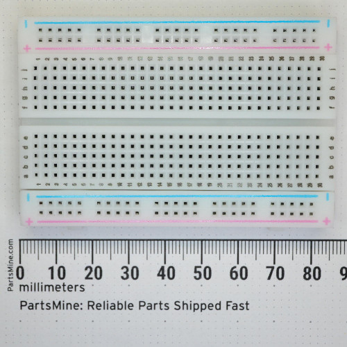
Designed to match standard half-size solderless breadboards, this 5.2 x 8.9 cm prototype PCB provides a direct transfer from temporary jumper-wire mockups to permanent, soldered hardware. The layout provides 30 numbered rows of five-hole tie points across columns A through J, flanked along both long edges by dual continuous power rails.
Key Features
- 5.2 x 8.9 cm outer dimensions matching half-size breadboard footprints
- Standard 2.54 mm (0.1 in) hole spacing for DIP ICs, headers, and discrete components
- 30 numbered rows divided into columns A-E and F-J across a center channel
- Dual continuous positive and negative power distribution rails on both long sides
- Gold-plated through-holes with durable black solder mask finish
- Two center and four corner mounting holes for mechanical fastening
Applications
- Transferring solderless breadboard microcontroller and sensor circuits into permanent hardware
- Prototyping custom audio effects circuits, guitar pedals, and synthesizer modules
- Assembling dedicated point-to-point test fixtures and breakout cards for bench testing
Frequently Asked Questions
Does this board have the same trace connections as a solderless breadboard?
Yes. The five holes in each numbered row (A-E and F-J) are electrically connected, and the power rails run continuously along both outer edges, directly mirroring standard solderless breadboard routing.
What is the pin spacing?
The through-holes are arranged on a standard 2.54 mm (0.1 in) grid, accepting standard DIP integrated circuits, pin headers, and through-hole passives.
Will a standard 0.3-inch DIP integrated circuit straddle the center channel?
Yes. The center divider spacing matches standard 0.3-inch DIP IC socket widths, leaving columns A-E on one side of the chip and F-J on the other for breakout connections.
Moving a circuit from push-in breadboard to soldered fiberglass is the exact moment an experiment turns into a tool. Route your traces, flow the solder, and put it in an enclosure that never comes unclipped.