What is H-Bridge?
H-Bridge is a circuit that is designed to change/reverse direction of current flow. It is usually used for changing direction if motors specially in robotics. It is also used in traditional inverters for inverted wave generation.
H-Bridge is easy to design and develop, it can be made using transistors (preferably BJTS or MOSFETS), diodes and a few more electronic components. Internet and technology has made it easy to find suitable components and simulators for a custom design.
Components required for low power H-Bridge:
All major electronic components required for making H-Bridge are available at PartsMine.com along with various alternate components with same specifications.
4 x Transistor - 2N3903
4 x Switching Diodes - A6
4 x Resistors - 10K Ohm
2 x Push Buttons
1 x Battery - 9v
1 x 9 volt battery clip
1 x Toy Motor
BJT 2N3903:
BJT 2N3903 serves as a switch, when voltages are applied on its base, it enters active mode and the current flows through collector and emitter terminal and when no voltages are applied on its base, it acts as open circuit and no current flows through it.
Switching Diode A6:
Switching diode A6 does not allow reverse flow of current. Here it is used as a flyback diode for short-circuit discharge path hence protecting circuit.
Resistor 10KOhm:
A 10KOhm resistor is connected in pull down configuration with the base of each transistor to ensure the logic signal given to respective transistor base is 0 in case no logic is provided to it. It is important as in some cases the can get charged even if it is touched with fingers and this results in activation of transistor which causes malfunction.
Push Button:
Push Buttons are like our door bell buttons, when pressed, they activate and upon release they deactivate.
Battery 9v:
A 9v battery is used for powering motor and transistor bases.
Toy Motor:
Toy motors are low power simple dc motors used in toys. Since our H-Bridge is offers control of only low powered motors, we are bound to use only low powered dc motors such as a toy motor.
Schematic Diagram and Connections:

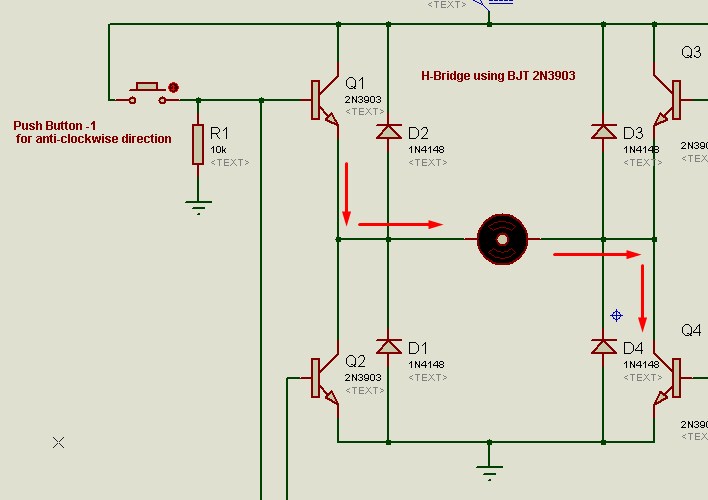
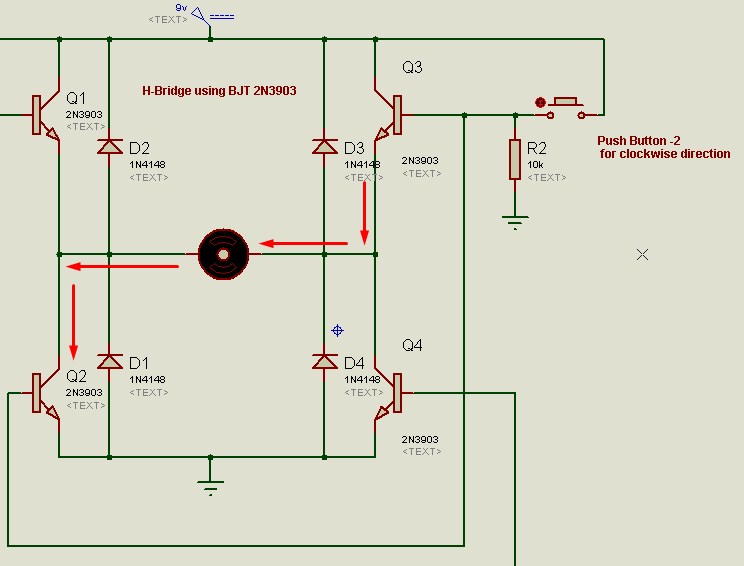
Connect all electronic components as described in schematic diagram. While making connections, do not connect battery. First connect all components, use continuity feature of DMM to check if all connection are according to schematic diagram. Make sure the bases of transistor Q1 and Q4 are connected and the bases of transistor Q3 and Q2 are connected. If all connections are appropriate, then connect battery terminals.
The best approach for making this project would be first simulating it on a software like Proteus or Multisim. Alternatively you can also find an online simulator, internet and technology has made it possible to simulate circuits online.
How it works?
When push button-1 is pressed, voltages are applied on bases of transistor Q1 and Q4 which causes current flow through these two BJTs while Q2 and Q3 remain inactive, since in this case current enters from left terminal of motor and leaves from right terminal of motor, the motor moves in an anticlockwise direction.
 When When push button-2 is
pressed, voltages are applied on bases of transistor Q2 and Q3 which causes
current flow through these two BJTs while Q1 and Q4 remain inactive, since in
this case current enters from right terminal of motor and leaves from left
terminal of motor, the motor moves in clockwise direction.

What’s next?
If you have successfully built your own H-Bridge, now is the time to build a high power H-Bridge for a simple remote controlled robot. You can use MOSFETs like IRF Z44 for running high power motors. Simply replace 2N2903 with IRF Z44 and there you go!

